Date published: 2020-07-22
Using an MGEN v2 Autoguider on a Losmandy mount with 492 Digital Drive System
Why I bought a Losmandy GM8 mount

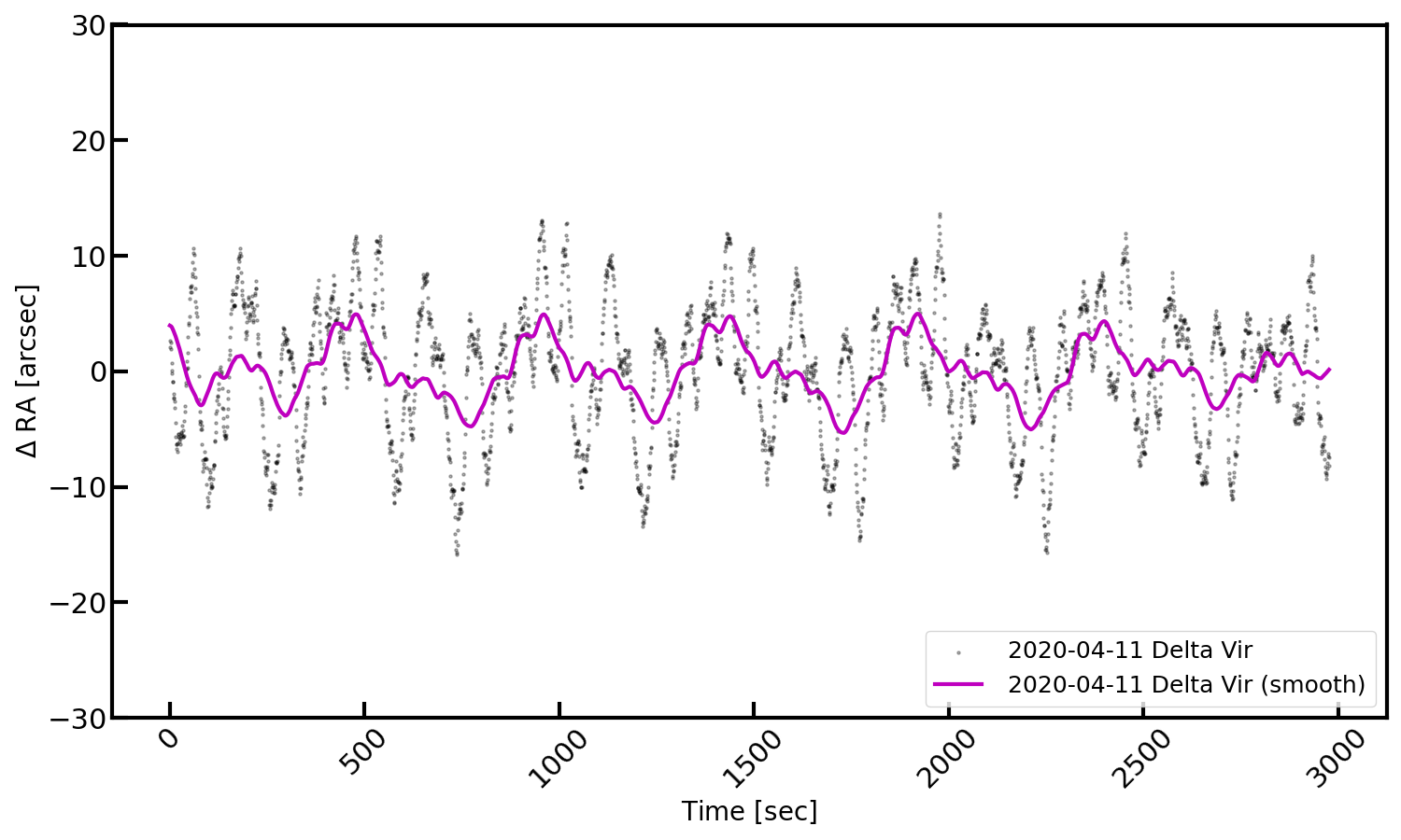
For some time already, I was looking for a stable and accurate mount as basis for astrophotography when traveling with big tele lenses (in the range of 400-600mm at f/4). I have previously owned Skywatcher’s EQM-35 Pro and EQ5 Pro mounts, but was never really happy with them. Not only they had large non-sinusoidal periodic errors, but also they were unsuitable for long exposure times, mainly due to low quality declination axis. These mounts often show large jumps in declination that are too large to be handled by autoguiders (see Figure 1 for an example of auto-guiding my EQ5 Pro). I invested much time to re-grease, adjust backlash, ideally balance the lens/camera, but nothing really helped to resolve the issue. Thus, I finally decided to buy something else that suits my purpose. As Losmandy mounts have a good reputation, and I was lucky to get a used one (GM8) with tripod, stepper motors, the 492 Digital Drive System and polar scope for less than 800 EUR, I decided to give it a try. If I had known about the trouble the 492 control box has with Lacerta’s MGEN autoguider (which is my favorite autoguiding system), I probably had made a different decision. So, here is the story about how I modified a Losmandy 492 control box to make it work with Lacerta’s MGEN v2 autoguider.
Servicing an old Losmandy GM8
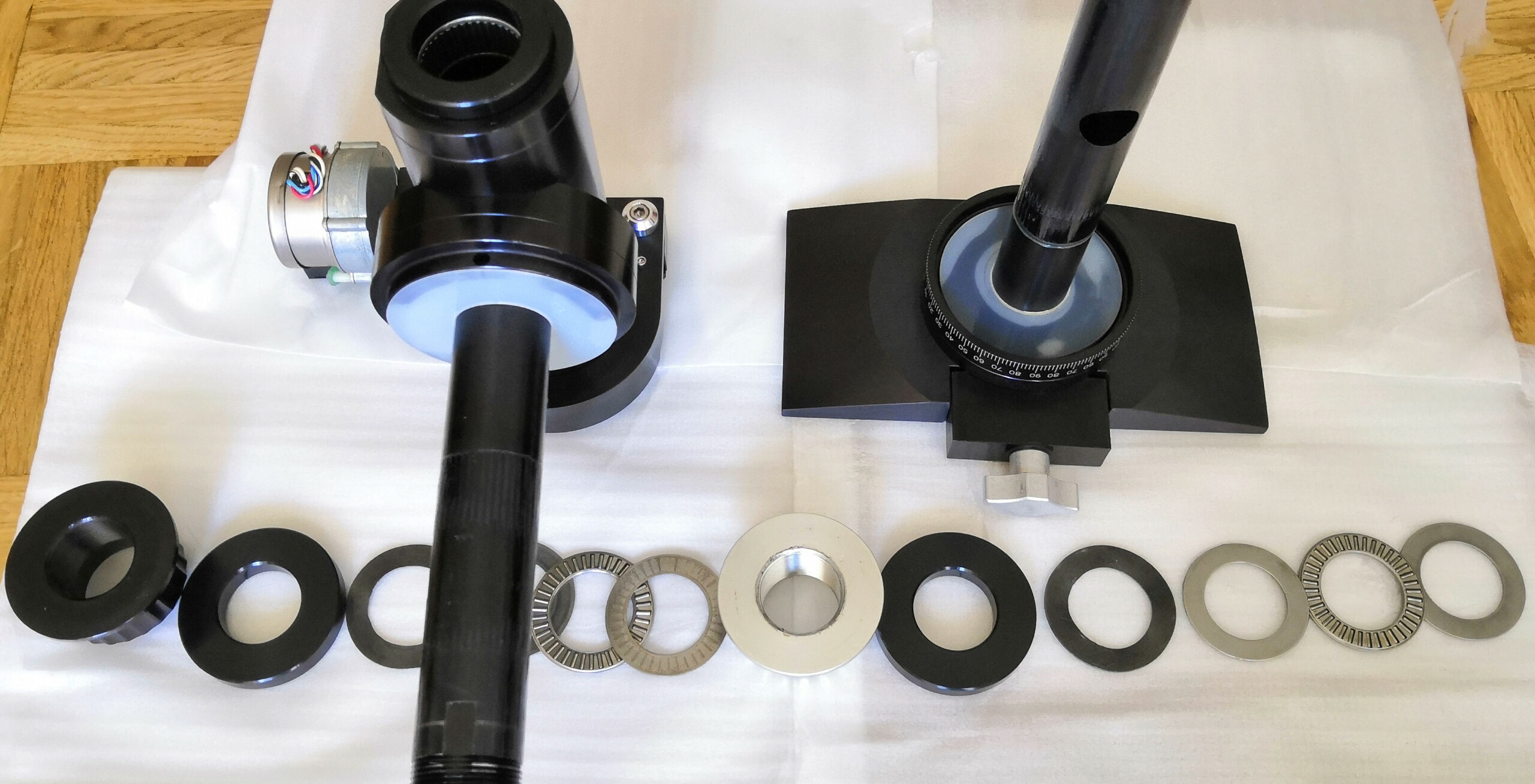
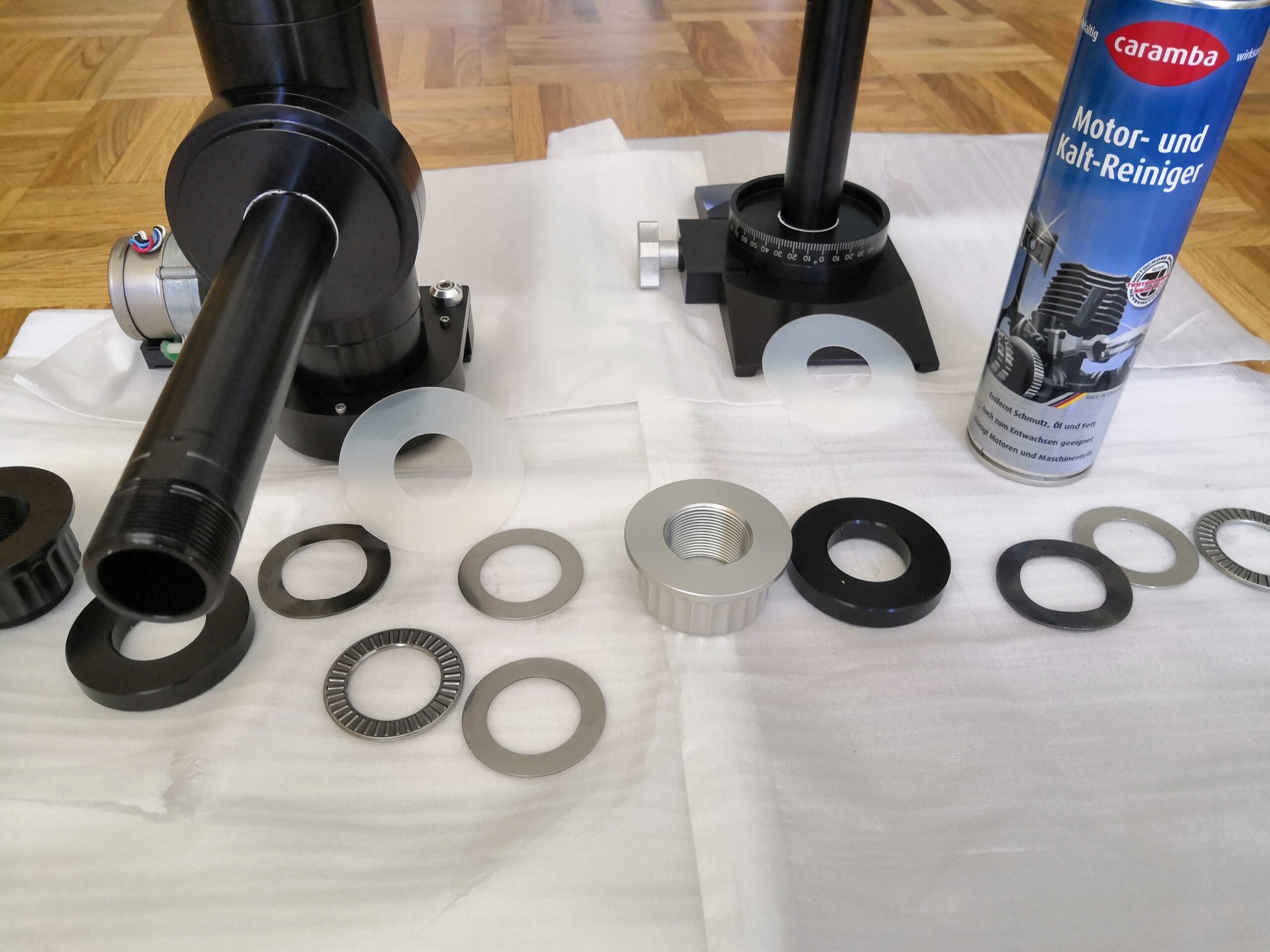
The Losmandy GM8 I got was in an overall good condition, with only minor signs of use. However, I have recognized that it was really hard to lock the axes using the clutch knobs. This is a well-known behavior that is also reported on the manufacturer’s website. Hence, the first thing I did was to disassemble, clean and re-grease the mount (see Figures 2-3). One can easily find instructions for the procedure on the internet, so I do not give more details about it here. Once finished, the mount was ready to be loaded with a small telescope.
The Periodic Error and other shortcomings
Using my MGEN v2 autoguider (with firmware 2.61) attached to a f=240mm guide scope a first test of the GM8 under night sky was performed. After polar alignment with the polar scope, the mount was pointed towards Zeta Peg (DEC +11°), a suitable star near the celestial equator for measuring the mount’s periodic error (PE). Without actually autoguiding (performing corrections), the PE was recorded using the “Savepos” option (to be found under “more” on page 5 in MGEN’s autoguiding menu). The measurements are shown in Figure 4. The PE is best seen after smoothing the data and its amplitude is roughly +/-8 arcsec. However, there is another high-frequency signal present with a much larger amplitude of +/-20 arcsec. Given the large amplitudes at short periodic lengths this seems problematic for autoguiding and long exposure times. For that reason, I decided to make some improvements: exchanging the worm bearings to ABEC-7 quality and sanding the worm bearing blocks. That way, the amplitude of the high-frequency signals was reduced to approximately +/-10 arcsec (see Figure 5). I describe the whole procedure of reducing the PE in a future post, since this article is only about how to modify a Losmandy 492 control box to actually work with the MGEN autoguider.

MGEN fails in guiding a Losmandy GM8 with 492 Digital Drive System
At this point, it is important to note that Losmandy’s 492 Digital Drive System (DDS) is incapable of processing simultaneously occuring ST-4 signals. The axes can be moved only in one direction at a time. For that reason the MGEN has a setting called “Exclusive AG out” (which is found in the “Misc” menu under “Mode settings”). This switch must be checked in order to separate signals in time for each direction.
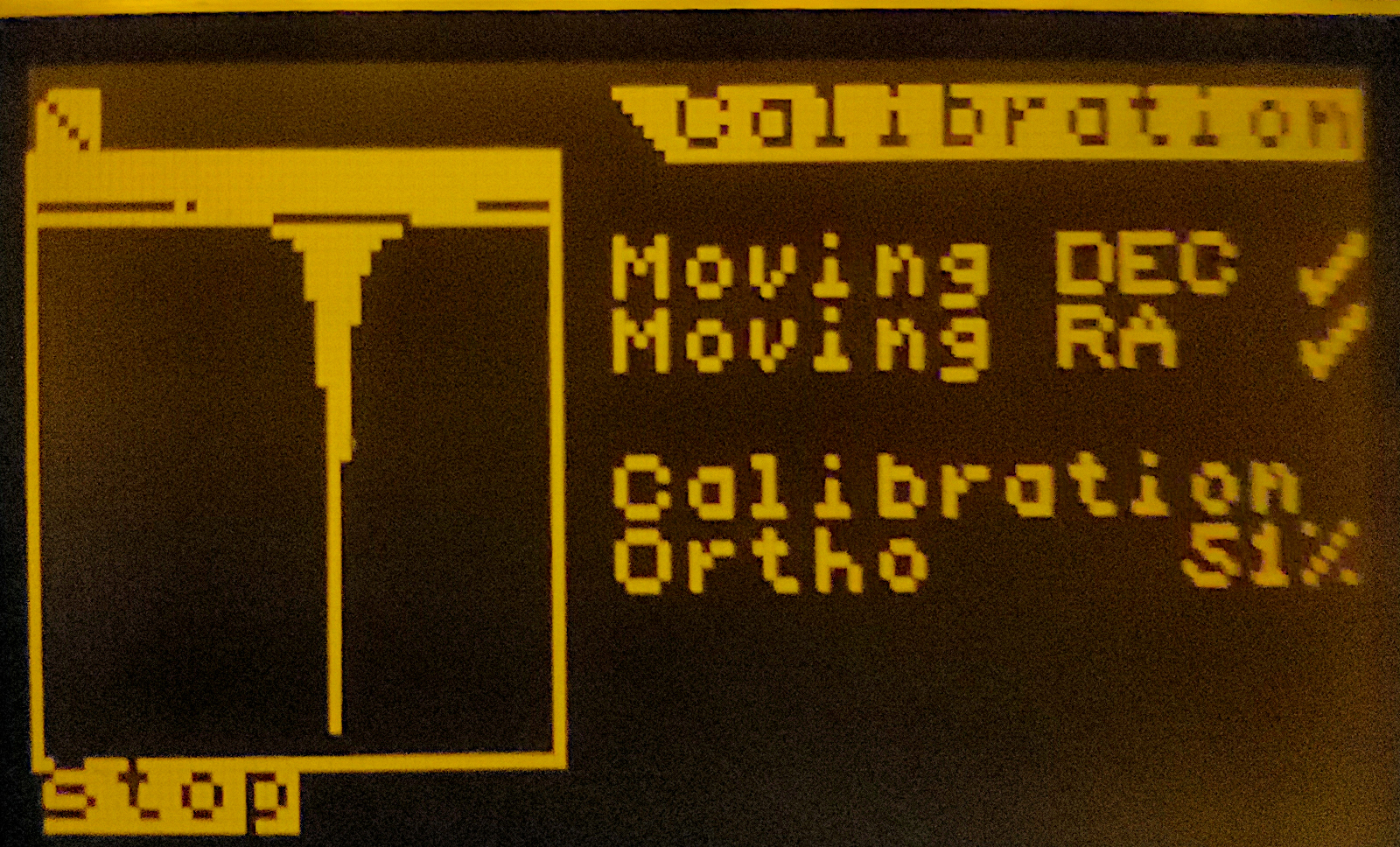
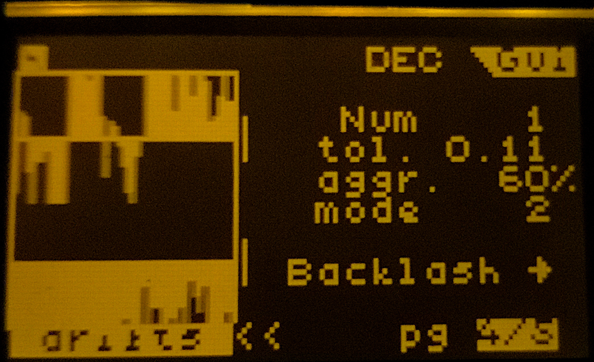
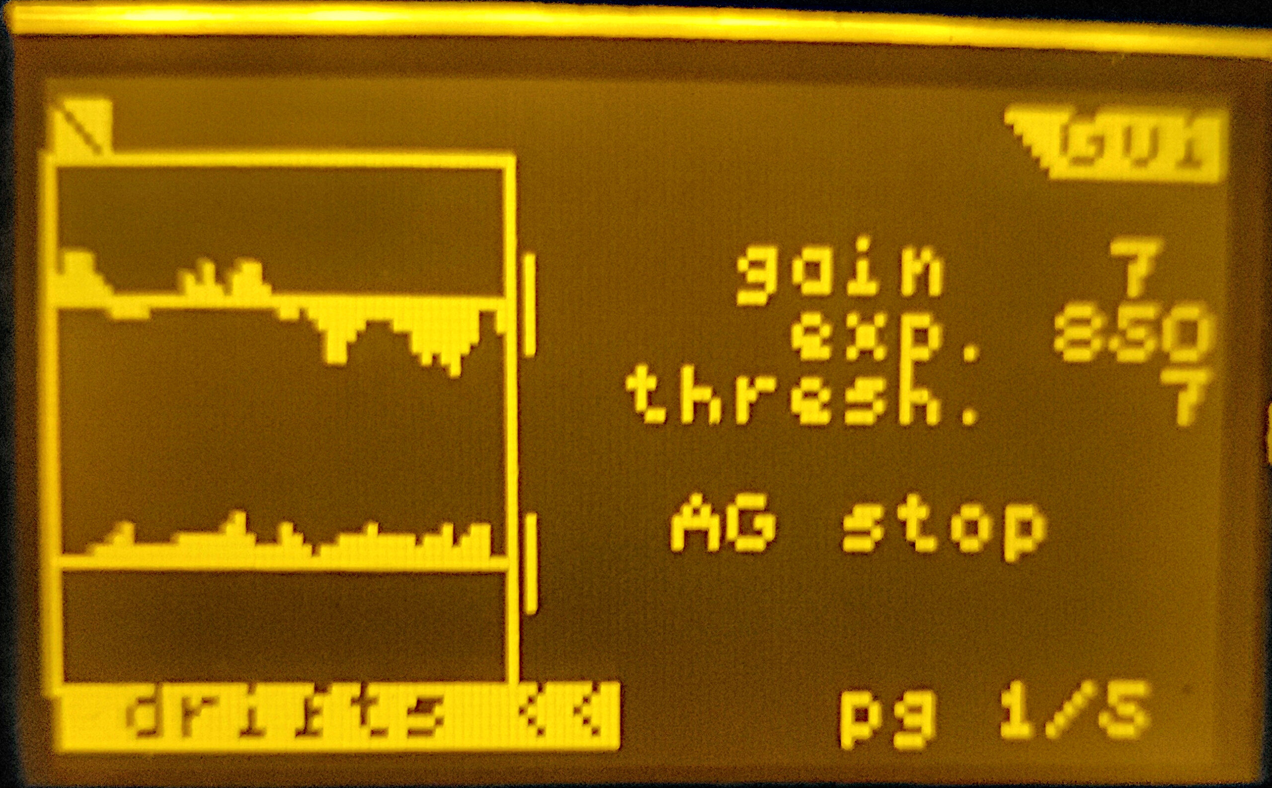
Now I was eager doing astrophotography with the mount, but soon I noticed the next drawback: The MGEN’s calibration procedure ended either with an error or very poor “ortho” values. Also, the calibration took unusually long (few minutes). One would expect ortho values between 95-100%, but what I got was far from that (see Figure 6). And when turning on the guiding, the stars would drift far off the limits (see Figure 7). What was going on? I realized that the autoguider is programmatically sending correct ST-4 signals, but the mount was not reacting to it. When using the MGEN as handcontroller (via its “Manual” mode on page 2 of the autoguiding menu), the mount was not moving in any direction (RA+, RA-, DE+, DE-). However, intermittently at least one or two directions were working.
I was first checking connections: the ST-4 cable from MGEN to the HC/CCD socket on the 492 Digital Drive System and the cables from the mount to the motors. But they were totally fine, the problem must be caused by something else.
Analysing the problem between MGEN and Losmandy 492
Some time and many “trial-and-error” attempts later, I could tell that both devices, the MGEN and the 492 control box were properly working on their own: Controlling the mount with the handcontroller (HC) worked just fine, but when connecting the MGEN instead of the HC only some or none of the directions were functioning. On the other side, the MGEN was properly working with other mounts, e.g. with my Skywatcher NEQ6. Additionally, I have tried another MGEN and also another 492 box. All tests led to the same failure. Either none or only some of the directions were working when controlling the GM8 with the MGEN.
Finally, using a y-connector cable plugged into to the HC/CCD socket, I measured the voltages on the four ST-4 pins (RA+, RA-, DE+, DE-). With the MGEN attached and no button pushed, the level was 2.5V on all four pins, which is totally fine for CMOS HIGH level. But, once a button was pushed the voltages were going down to 1.7V on the three unrelated pins and 0.4V on the activated pin. On the other side, with the HC attached and one button pushed, the voltages on the unrelated pins remained constant at 2.5V and the activated pin showed exactly 0.0V.
Looking into the datahseet of the main chip used in Losmandy’s 492 device, I figured that, while 0.4V should still be recognized as LOW, the EPROM needs at least 2.0V for HIGH. Given that with the MGEN attached, only 1.7V are provided on three pins, the logic would have trouble to interpret the input.
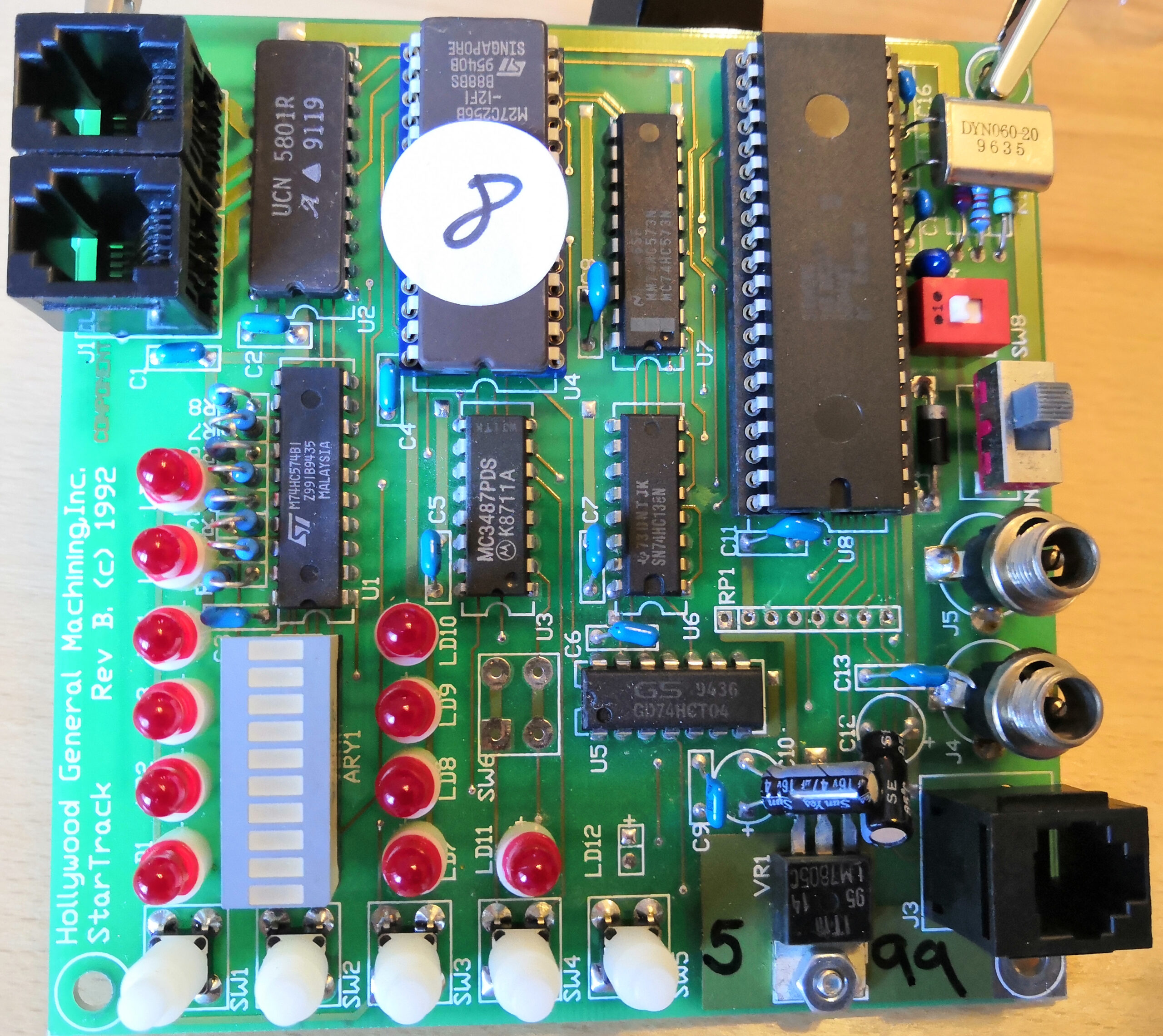
So, what causes the voltage break-down when using MGEN instead of the HC? I knew that the MGEN v2 is internally using opto-couplers for DC isolation. Thus, it seemed obvious that the opto-couplers have a relatively high internal resistance, or likewise the pull-up resistors in the 492 box have relatively low values, causing the 2.5V to be split accordingly. An examination of the 492 board revealed an array of resistors labelled “RP1”. I reckoned that these are the pull-up resistors and indeed, their values were very low, with only 470Ω.
Solution: Exchanging pull-up resistors in the Losmandy 492 DDS
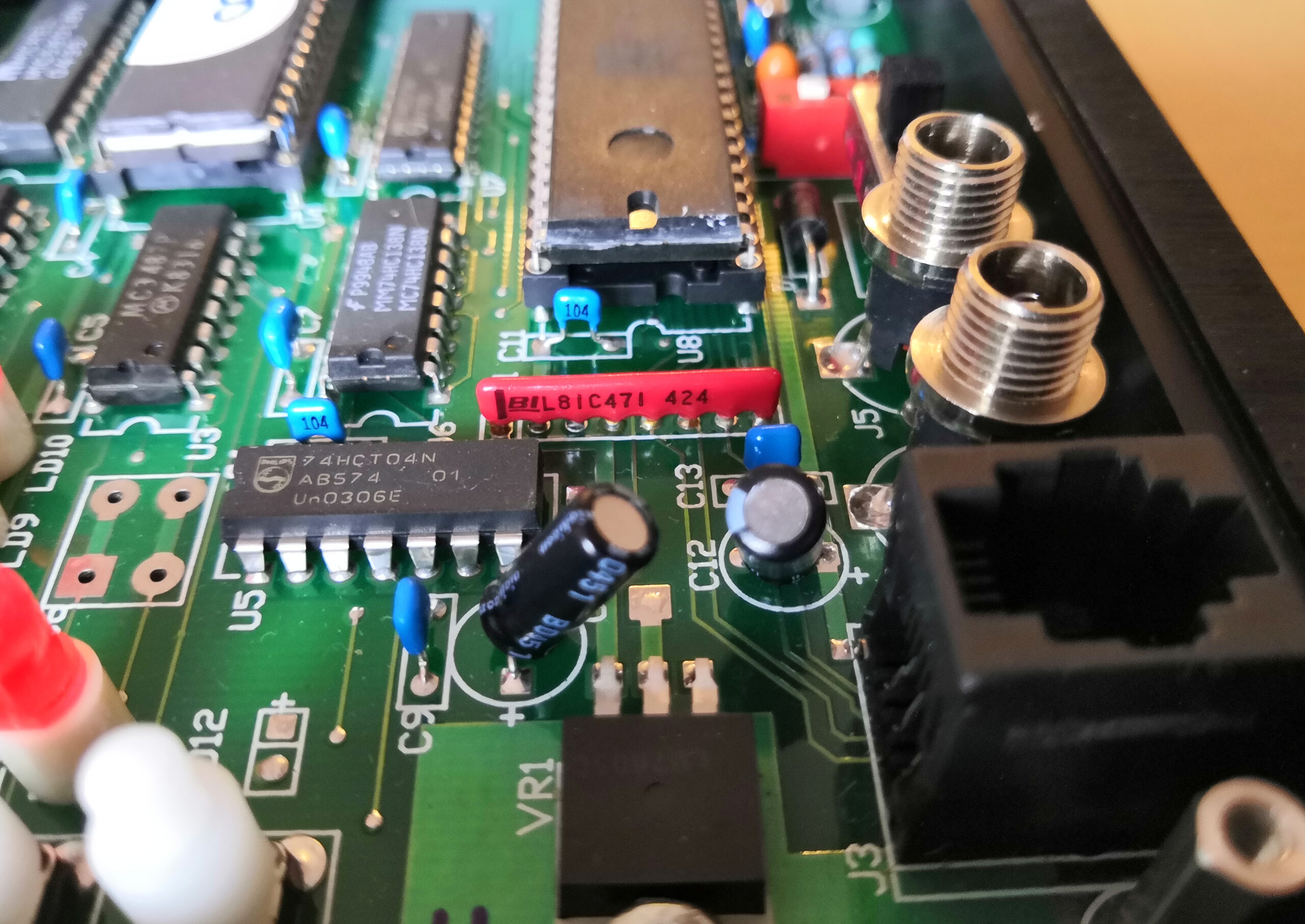
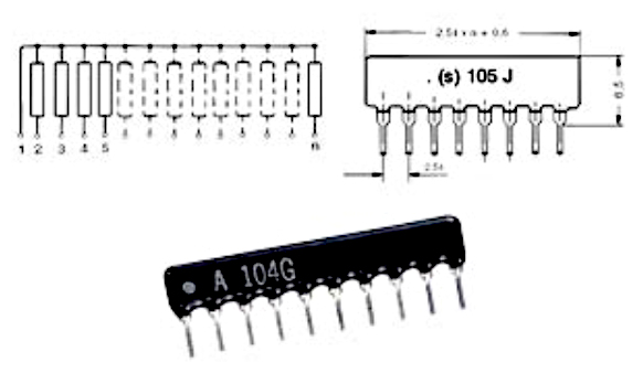
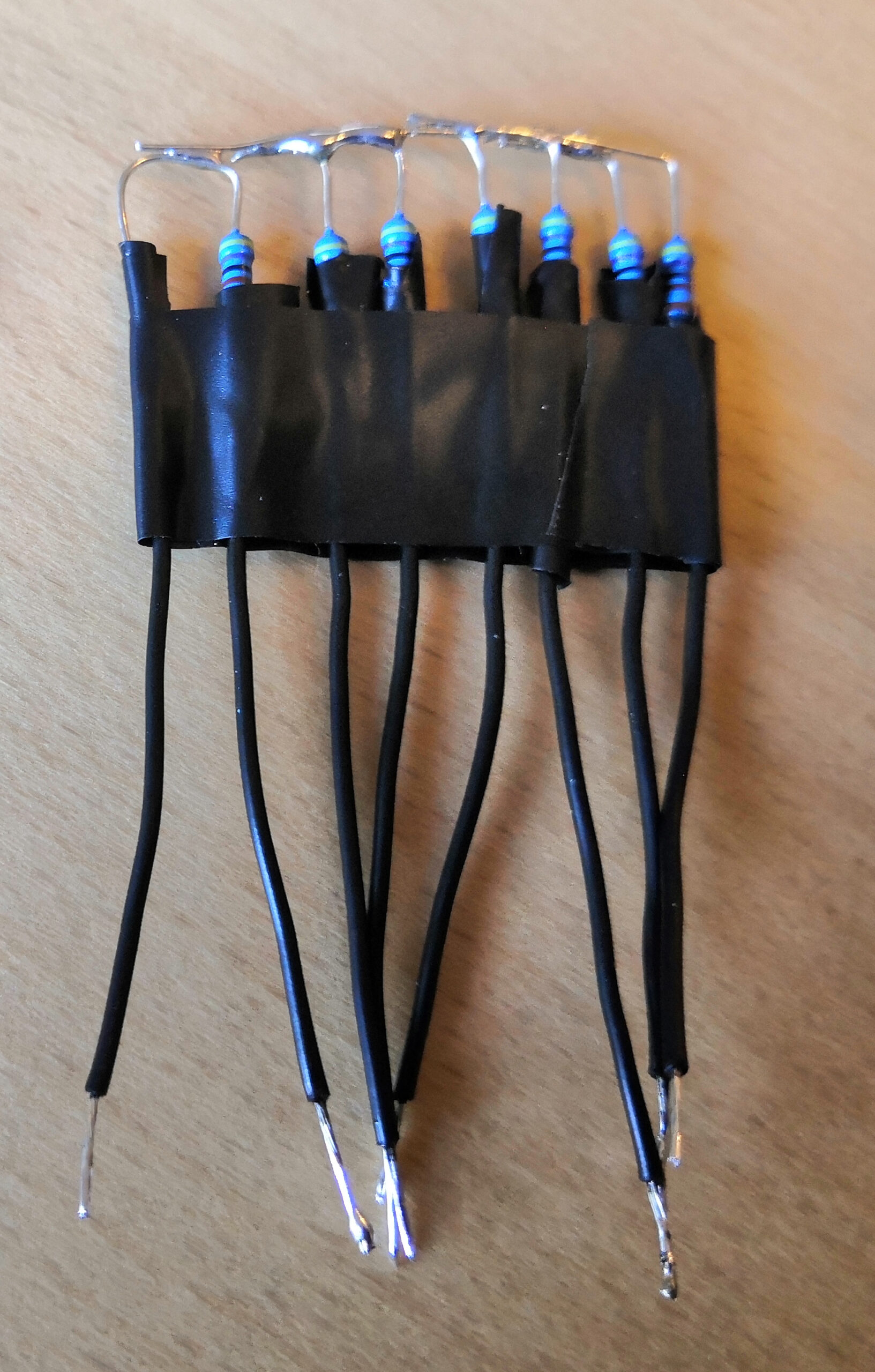
Replacing RP1 on the 492 board with a resistor network in the range between 4.7kΩ and 10kΩ, e.g. this one, should thus solve the problem of voltage drop. However, before ordering something, I wanted to make sure that this was indeed the final solution I was looking for. Since I did not have a 8-pin resistors network on hand, I just used “normal” 4.7kΩ resistors and soldered them together (see Figures 8-12). After that, the MGEN v2 was capable of moving the axes of my Losmandy GM8 with 492 control box in all directions. And “ortho” values during calibration are now 99-100%.
Conclusion
Finally, I am pleased with my GM8. However, its tracking curve still shows +/- 10 arcsec peak-to-peak values at periodic lengths (much) shorter than the worm periodic error, but the mount may be guidable with MGEN (see Figure 13). This mount thus provides a good basis for astrophotography. However, I plan to make some more improvements to reduce the high-frequency peaks as they still unnecessarily blow up the star images when doing long exposures.

Additional Reading:
The modifications described here were previously discussed in German on astronomie.de:
https://forum.astronomie.de/threads/problem-mgen-2-mit-losmandy-492.291130/ and https://forum.astronomie.de/threads/losmandy-gm8-schneckenfehlermessung-mit-mgen-hohe-frequenzen-mit-hoher-amplitude.280712/